
General description of the hot gas generators
We build hot gas generators and industrial combustion chambers on the basis of many years of research and development. Our hot gas generators can be used for drying a broad range of products such as cement, limestone, animal feed, grass, etc.
The burner is primarily designed for the combustion of pulverised materials, such as lignite, biomass, sludge, etc. But gaseous and liquid fuels can be used as well. Depending on the design, automatic switching between fuels is possible without modifications and the associated downtime. The use of alternative fuels allows for considerable cost savings and long-term planning. In regions where lignite is mined, pulverised lignite is a cost effective and environmentally friendly alternative.
Even the largest hot gas generator can be built without refractory liners. They are durable and completely impervious to rapid temperature changes. The use of return gas is possible and, in addition to lowering fuel costs, also saves filter costs.
We are able to delivery the complete system as a turn-key solution, offering you a maximum degree of planning reliability.
The burner design is the reason for the many positive characteristics. In addition to the compact footprint, the resulting flow principle provides the burner with additional unique operating characteristics.
Functional description
The combustion air flows through a radial blade cascade helically towards the exit. Here, the combustion air returns about one half of the flow radially inwardly back to the inlet. The backflow juts to the faceplate outwards and flows with the fresh air further to the exit. By backflow an intense tubular turbulence forms, in which the fuel is introduced. The central backflow constantly brings hot flame gas to the fuel inlet and ensures constant post ignition. The flame is separated by a very stable cold air layer of the conical wall, whereby the outer wall remains cool. The combustion chamber is additionally cooled from the outside by the cool air blower. The system requires no firebrick lining.
The impulse burner used, because of its structure and its flow pattern, ensures reliable combustion and high burnout already in the combustion chamber.
The downstream mixing chamber serves to increase the retention time and for setting the discharge temperature. The mixed air is fed via an annular gap to cool the mixing chamber and is first fed to the hot gas at the end. ln combination with the burner and the design of the mixing chamber compliance with the Clean Air Act is ensured without secondary measures.

Simplified overview:
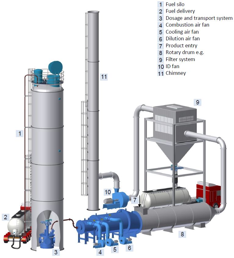
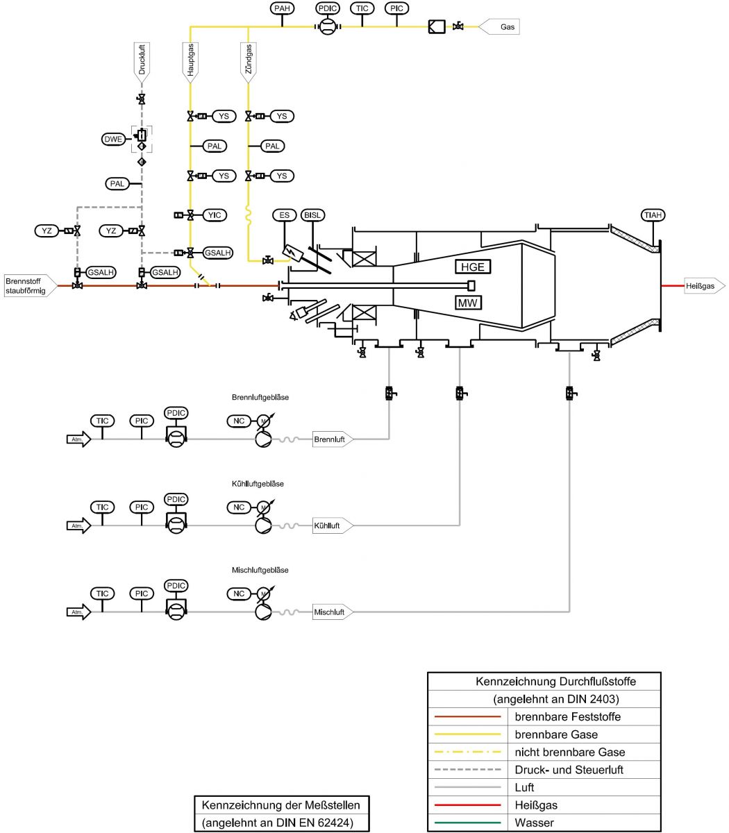
Flow diagram of a typical "combo burner" type hot gas generator.
Two different types of fuel, in pulverised and gaseous form, can be used with this setup.
Technical details
The hot gas generators are designed and dimensioned according to customer requirements,
so the following benchmark data can only serve as a general reference.
| Fuel: | Pulverised, gaseous, liquid |
| Output range: | 100 kW to 50 MW |
| Control range: | 1 : 3 ... 1 : 20 |
| Full load from a cold start: | approx. 1-2 min. |
| Hot gas temperature | fuel and process-dependent |
| Installation size: | Output dependent (3 MW approx. LxWxH 6x2x2 m) |
The gallery contains 11 pictures.
Please click a thumbnail to enlarge the picture.


.jpg "Picture: easy integration of our system into a process control system (PCS)")


